
TM 10-7310-282-10
0003 00
Ice Machine
Ice Production in 24 hours ................................................................................................... 477 lb (216.4 kg)
Compressor Horsepower (hp) .............................................................................................................. 1 hp
Refrigerant ............................................................................................................................................ R-502
Electrical Requirements ........................................................................................... 208 VAC / Single Phase
Bin Capacity ......................................................................................................................... 40 US gal (155 l)
Condenser Cooling ........................................................................................................................ Air Cooled
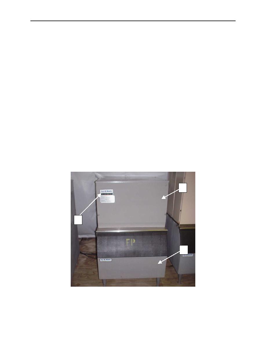
The ice machine is composed of two major assemblies, the ice maker (1) and the storage bin (2). The
ice maker is connected to the Force Provider Electric Kitchen water manifold for potable water. The ice
maker operates within a timed harvest cycle. In the beginning of the cycle, the water is metered into a
reservoir, from which it is pumped up and over the evaporator. The water is recirculated in the reservoir
until the end of the harvest cycle.
At the next point in the cycle, the timer activates a hot gas valve, which diverts hot refrigerant from the
condenser to the evaporator, freeing the ice from the evaporator. The ice then falls into the storage bin,
from which the ice is dispensed as needed.
The final point in the cycle is a brief delay, which ensures that all ice has cleared the evaporator grid. The
average time for a harvest cycle is approximately 18 to 20 minutes, depending on ambient temperature,
incoming water temperature, and the volume of ice dispensed.
The storage bin is cooled by the ice maker, but has a separate thermostat control. A drain tube is
provided to accommodate melting.
An external indicator panel (3) is provided to allow the operator to monitor the status of the ice maker.
1
3
2

