TM 10-7360-204-13&P
4-18 Change 11
4-9.9
FRAME.
If the frame requires replacement, all disassembly procedures in paragraph 4-9.1 through 4-9.6 must be accomplished.
4-9.10
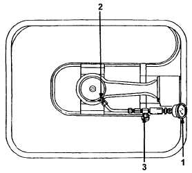
SAFETY VALVE DEVICE.
a.
General. The safety valve device is designed to release if fuel tank air pressure exceeds approximately 60psig. It
will reset at approximately 35+ 10 psig.
b.
Removal.
(1)
Remove top shield (para 4-9.1).
(2)
Remove generator assembly (para 4-9.2).
(3)
Remove burner, fuel feeder tube, and
bottom shield (para 4-9.3).
(4)
Remove air pressure gage (1).
(5)
Remove locking nut (2).
(6)
Loosen and remove adapter (3) from fuel
tank assembly.
(7)
Remove safety valve device.
c.
Replacement. Reverse removal procedures.
NOTE
The safety valve device is stocked only in kit form. If the device is being
installed on existing units, follow procedures outlined above.
4-9.11 SAFETY VALVE DEVICE KIT INSTALLATION. (Refer to Figure 4-3)
a.
Present production M2 Burner Units have a safety valve device installed during manufacture.
b.
The safety valve device is an assembly stocked only in kit form, which is connected between the U Tank and the
mixing chamber.
A safety valve device should be installed on all M2 and M2A burner units as
an added safety feature.
c.
Instructions for installation and testing, which are packaged in each kit are as follows:
(1)
Release pressure from tank and drain fuel tank (
para 4-9.6 and 4-9.8).
(2)
Remove top shield, generator, burner, and bottom shield (
para 4-9.1 and 4-9.3).
(3)
Place unit in the horizontal position and remove mixing chamber (
para 4-9.3).
WARNING