
MWO 10-7360-206-30-1
1) Attach the plug (item 1) to one end of 1-foot cable (item 7), stripping cable jacket and
wire as necessary. Ensure green to ground, black to brass, and white to silver terminals.
(Figure 12).
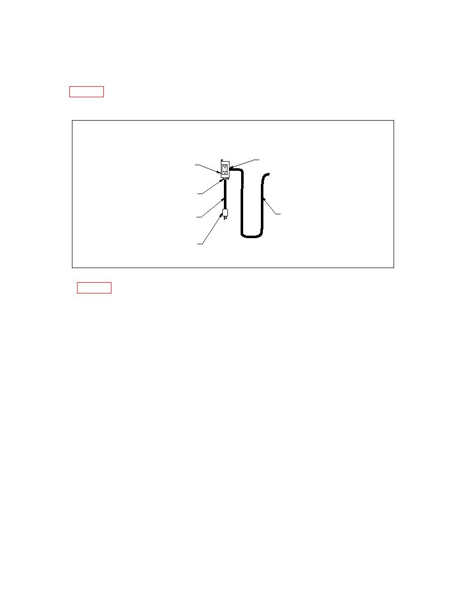
Use stain relief connector (item 5)
Outlet box (item 2), GFCI (item 4), and
on back of outlet
watertight cover (item 3)
Strain relief connector (item 5)
Five foot cable (item 6),
One foot cable (item 7),
attach to GFCI using terminals (item 10)
attach to GFCI using terminals (item 10)
Plug (item 1)
Note: Green to ground, white to silver, black to brass.
Figure 12. Assembly of feeder cable harness.
2) Strip back approximately 3 inches of cable jacket and inch of each wire jacket from
the other end of the 1-foot cable and attach terminals (item 10) to each of the three wire
ends.
3) Pass the end with the terminals through the strain relief connector (item 5) and install
the 1-foot cable assembly into the bottom access hole of the outlet box (item 2).
4) Strip back approximately 3 inches of cable jacket and inch of each wire jacket from
one end of the 5-foot cable (item 6) and attach terminals (item 10) to the each of the three
wire ends.
5) Attach mounting tabs supplied with the outlet box to the outlet box.
6) Insert the end of the 5-foot cable with the terminals through the strain relief connector
(item 5) and install the 5-foot cable assembly into the rear access hole of the outlet box
(item 2). Make sure the threads of the strain relief do not extend into the inside of the
box.
7) Attach the 5-foot cable to the load side and 1-foot cable to the line side to the GFCI
duplex outlet (item 4). Insure green to ground, black to brass, and white to silver
terminals of the outlet. Do not attach the receptacle at this time.
13
